This small tutorial demonstrates graphics programming by writing a little program for the YASEP, step by step, with a simple example : filling the framebuffer with a pseudo random colour.
Requirements and Assumptions:
⚠ The code doesn't work if the framebuffer window is not open. ⚠
Don't forget to open it (click here) and make sure it is linked to the same memory map as the editors.
To fill the screen you have to address all of the pixels using a loop.
Start by assigning registers for this operation:
;  R3 : a counter
;  A1 : stores the return address for the loop
; Note : this is a comment. Not necessary,
; but useful for navigating the program.
Then we must fill register R3 with the right number of iterations. The YASEP is configured as 32 bits and the framebuffer uses 24 bits per pixel (with 8 most significant bits unused), therefore it's possible to access 1 pixel at a time.
With a framebuffer of 256*256, that makes 65,636 pixels and therefore there must be 65536 iterations to fill the whole frame buffer. The value is decremented each pass.
mov 65536 R3
We must also writte an instruction that saves the loop address to allow the loop to return to the right place in the program.
We calculate 4+PC then put the result in A1. The PC register contains the address of the current instruction. We create a pointer to the following instruction (PC+4) so we can jump later back to the right place in the loop. We add 4 because this instruction word is 4 bytes long, but beware there are also 2 byte instructions, so read the documentation for the instructions you're using.
add 4 PC A1
And then decrement the counter.
add -1 R3
Then copy A1 into the PC (Program Counter) if R3 is not zero (NZ).
mov A1 PC NZ R3
And finally halt the CPU when the program is complete.
HALT 1
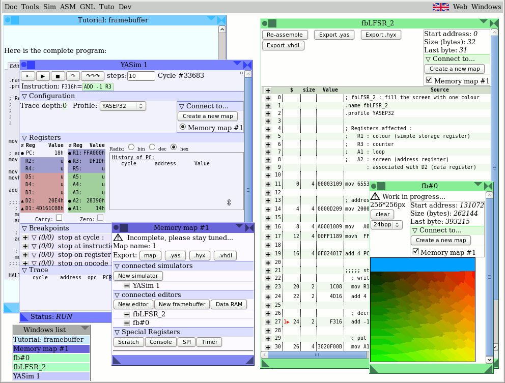
Here is the complete program: :
; fbLFSR_1 : loop 65536 times
.name fbLFSR_1
.profile YASEP32

; Registers affected :
;   R3 : counter
;   A1 : loop

mov 65536 R3

add 4 PC A1

;;;;; start of the loop ;;;;;
  ; decrement the counter
  add -1 R3

  ; move A1 into the PC if R3 is not equal to 0
  mov A1 PC NZ R3
;;;;;; end of the loop ;;;;;;

HALT 1
Now, we access the framebuffer, by calculating the address of the pixels so we can change their value (to a single colour).
We start by assigning more registers:
;  R1 : colour (R : simple storage register)
;  R3 : counter  \from the previous chapter
;  A1 : loop     /
;  A2 : pointer to the screen (A : address register)
;       associated with D2 (D : data register)
We now point A2 to the beginning of the framebuffer:
mov 20000h A2
The framebuffer address could change arbitrarily, check that this corresponds with the address defined at the top right of the framebuffer window.
Then decide the colour of the pixels:
For this, you have to place #00A0FF (the HTML code of the colour) in R1. We start by restructuring the byte order in the word:
We manually convert the RGB colour into BGR because the YASEP is "Little Endian" (the lower byte of a register goes to the first address) and the red component is the first byte position in the pixel word. The colour value will ultimately be 00 A0 FF 00 (the first two 0 are not used but they are required to fill a 32 bits word).
The YASEP cannot load 32 bits of immediate data at once, it's therefore necessary to have a sequence of instructions that change each of the 16 bit half words at a time. First the value A0 00 is placed in the rightmost significant 16 bits with MOV then (00) FF in the left most significant 16 bits using MOVH..
  mov   A000h R1
  movh  FFh   R1 ; #00A0FF : sky blue
Then we write the color in the framebuffer with MOV and advance to the next pixel (4 bytes later) with ADD 4 A2:
  mov R1 D2
  add 4 A2
Here is the complete program:
; fbLFSR_2 : fill the screen with one colour
.name fbLFSR_2
.profile YASEP32

; Registers affected :
;   R1 : colour (simple storage register)
;   R3 : counter
;   A1 : loop
;   A2 : screen (address register)
       ; associated with D2 (data register)

mov 65536 R3

; address of the framebuffer:
mov 20000h A2

mov   A000h R1
movh  FFh   R1 ; #00A0FF : sky blue

add 4 PC A1

;;;;; start of the loop ;;;;;
  ; write the colour in the framebuffer
  mov R1 D2
  add 4 A2

  ; decrement the counter
  add -1 R3

  ; put the contents of A1 into the PC if R3 is not equal to 0
  mov A1 PC NZ R3
;;;;;; end of loop ;;;;;;

HALT 1
This is what your screen should look like:
All of the subtleties of the maths are reduced to the constant chosen for the XOR operation, which is called a "polynomial". There are tables of valid 32 bit values that you can choose, and the 32 bit one used here comes from the CRC32 standard : 0x04C11DB7
For the pseudo-random number generator to function correctly, in addition to the choice of a working polynomial, you must also make sure that R1 is not initialized with the value 0. The colour "sky blue" is a convenient example of a non-zero value that R1 can be initialised with.
Registers Affected:
;   R1 : LFSR (colour)
;   R2 : polynomial
;   R3 : counter
;   A1 : loop
;   A2 : screen (Address Register)
;        associated with D2 (Data register)
We therefore initialize the LFSR's polynomial in R2.
  mov   1DB7h R2 ; LSB
  movh 04C1h R2 ; MSB
Like the blue sky colour, this is a value that doesn't fit in 20 bits, so it must be "cut in half" then loaded into R2 using a sequence of two instructions (MOV then MOVH).
... and then we generate a pseudo-random bit :
  add R1 R1 ; shift the register to the left by one bit
  ; and copy the most significant bit's value into the carry bit
Finally, if the Carry flag (coming from R1's most significant bit) is 1, XOR the result with the polynomial. This allows us to generate the pseudo-random bit in combination with the offset produced by the previous ADD:
xor R2 R1 CARRY
Here is the complete program:
; fbLFSR : fill the screen with
; a pseudo-random colour
.name fbLFSR
.profile YASEP32

; Registers affected :
;   R1 : LFSR (colour)
;   R2 : polynomial
;   R3 : counter
;   A1 : loop
;   A2 : screen (address register)
       ; associated with D2 (data register)

mov 65536 R3

; address of framebuffer:
mov 20000h A2

mov   A000h R1
movh  FFh   R1 ; #00A0FF : sky blue

; initialise R2 with the LFSR polynomial:
mov  1DB7h R2 ; LSB
movh 04C1h R2 ; MSB

add 4 PC A1

;;;;; start of the loop ;;;;;
  ; generate a pseudo-random bit :
  ADD R1 R1 ; shift R1 by one position
   ; to the left and copy the most
   ; significant bit into the carry flag

  ; If the carry flag is set, apply the polynomial
  xor R2 R1 CARRY

  ; write the colour into the framebuffer
  mov R1 D2
  add 4 A2

  ; decrement the counter
  add -1 R3

  ; move A1 into PC if R3 is not equal to 0
  mov A1 PC NZ R3
;;;;;; end of loop ;;;;;;

HALT 1
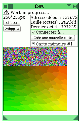
The result should look more or less like that :