The YASEP uses a 16-bits fixed-format instruction word with an optional 16-bits immediate field or a 16-bits extended word. This instruction format is identical for both YASEP16 and YASEP32 : YASEP32 can use 16-bits instructions, YASEP16 can use 32-bit instructions. There is very little difference and the instruction decoder must handle both instruction lengths.
Each instruction can contain :
These fields and flags are not all used at the same time. Some combinations are impossible by construction, some others don't make sense, others can be hidden by the assembler. However, a wide variety of instructions (an opcode followed by register names, immediate data or other flags) can be written by the user. This page explains what are the "instruction forms", how they are designed and when they are used.
An "instruction form" is named after the way it is written in assembly language. It is a sequence of letters that describe each used field :
The YASEP allows only a limited number of forms. The two least significant bits of each instruction determine how to interpret the operands and other fields. The 2 bits create 4 combinations :
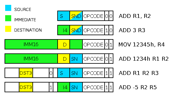
The YASEP instructions write the result of an operation (when any) to a register whose address is given by the si4, snd or dst3 fields, depending on the instruction form :
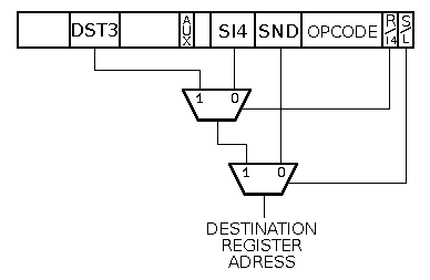
It is a bit unexpected that si4 becomes a destination register field in the long form. It is justified by the fact that snd is the only place in the datapath where operand complementation (the n of snd) can take place.
This system is probably a bit complex and could eventually make architectural development difficult in the far future. However, this is required to keep the instructions compact. Furthermore, in the datapath, what really counts (for performance) is the access time of the operands, not the destination address which can be computed at the same time as the ALU (a good dozen of logic levels). Since pipeline bypass is not considered as an architectural feature, we have more freedom with the fields and can get the most out of each bit, while still keeping the instructions orthogonal. The assembler deals where to put each field for us.
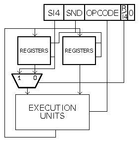
Let's start with the most simple instruction forms. The short instructions have their LSB cleared and are 16-bit long. This is enough for another flag, a 6-bit opcode and two 4-bit fields.
| 15 | 14 | 13 | 12 | 11 | 10 | 9 | 8 | 7 | 6 | 5 | 4 | 3 | 2 | 1 | 0 |
| si4 | snd | opcode | Reg | short | |||||||||||
| R2 | R1 | ADD | 0 | 0 | |||||||||||
| 15 | 14 | 13 | 12 | 11 | 10 | 9 | 8 | 7 | 6 | 5 | 4 | 3 | 2 | 1 | 0 |
| si4 | snd | opcode | Imm4 | court | |||||||||||
| -3 | R1 | ADD | 1 | 0 | |||||||||||
In practice, these 2 combinations can be used in 5 ways in assembly language, since any of these fields can be more or less useful depending on the kind of operation :
ADD R1 R2 ; R2 <- R1+R2This is the most common form, where si4 and snd are both register operands, and the result goes to snd.
ADD 2 R3 ; R3 <- 2+R3Another common form where si4 is used as an immediate value, so snd is used as both source and operand.
PUT R1 3 ; Send the contents of R1 to Special Register #3This is just another way of writing iR when the instruction uses the immediate value as a destination address. This syntax conforms to the first rule of the YASEP assembly language (the destination is always the last operand of the instruction).
Physically, iR is encoded as Ri :
 PUT A5 4 ; => 4762h
 GET 4 A5 ; => 4742h
The immediate "4" stays at the same place. However, it is better to stick to the general writing rules so the source operand is easier to spot, since it does not depend on the opcode.
NEG R1 ; internally : R1 <- 0 - R1It's also a short way to write that both si4 and si4 fields contain the same register address. The assembler will correctly fill the operand fields if the form is correct for the opcode.
CRIT 3 ; disable the interrupts during the 3 following instructionsNot used very often but sometimes necessary. si4 is used as an immediate value and snd is ignored.
NOP ; Nop operand needed, all fields ignored.This is an extreme case where no operand is needed : si4 and snd are ignored.
YASEP interprets the instruction as 32-bit long when the LSB is set to 1. The 16 lower bits are exactly the same as the short forms. The second LSB selects how to interpret the higher half-word :
| 31 | 30 | 29 | 28 | 27 | 26 | 25 | 24 | 23 | 22 | 21 | 20 | 19 | 18 | 17 | 16 | 15 | 14 | 13 | 12 | 11 | 10 | 9 | 8 | 7 | 6 | 5 | 4 | 3 | 2 | 1 | 0 |
| Imm16 | si4 | snd | opcode | imm16 | long | ||||||||||||||||||||||||||
| 1234h | R2 | R1 | ADD | 0 | 1 | ||||||||||||||||||||||||||
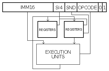
ADD 1234h R2 R1 ; R1 <- 1234h + R2This is another common form where the operands are snd (a register field) and the 16-bit immediate field. The destination register is given by si4.
GET 1234h R1 ; R1 <- SR[1234h]This form is used for the GET or MOV instructions. snd is ignored because only si4 (the destination address field) makes sense for the operation. The assembler also detects when the immediate address is larger than 4 bits and issues a long or a short form.
This is also used (in conjunction with the ALIAS_IRR flag) by the ROP2 group and the ADD/SUB instructions : this is similar to FORM_iR but with a 16-bit immediate operand. si4 and snd have the same value.
; Both are encoded the same way and perform the same operation :
 OR 1234h R1 R1
 OR 1234h R1
.profile YASEP32 ; the 4 MSB are ignored with YASEP16
 CALL 12345h R1
 MOV 12345h R1
PUT R1 1234h ; SR[1234h] <- R1This form is currently only used for the PUT instruction. It is the same as FORM_IR but the order of the operands is reversed at the assembly language level to obey the rule #1 : "the destination is written at the end of the instruction".
The extended forms reuse the short form's structure and add 16 bits for several additional features :
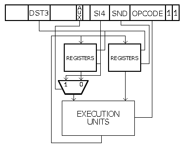
| 31 | 30 | 29 | 28 | 27 | 26 | 25 | 24 | 23 | 22 | 21 | 20 | 19 | 18 | 17 | 16 | 15 | 14 | 13 | 12 | 11 | 10 | 9 | 8 | 7 | 6 | 5 | 4 | 3 | 2 | 1 | 0 |
| dst3 | Reg | si4 | snd | opcode | Ext | long | |||||||||||||||||||||||||
| R3 | 0 | R2 | R1 | ADD | 1 | 1 | |||||||||||||||||||||||||
ADD R1 R2 R3 ; R3 <- R1+R2si4 (R1) and snd (R2) are both register operands, and the result goes to dst3 (R3).
| 31 | 30 | 29 | 28 | 27 | 26 | 25 | 24 | 23 | 22 | 21 | 20 | 19 | 18 | 17 | 16 | 15 | 14 | 13 | 12 | 11 | 10 | 9 | 8 | 7 | 6 | 5 | 4 | 3 | 2 | 1 | 0 |
| dst3 | Reg | si4 | snd | opcode | Ext | long | |||||||||||||||||||||||||
| R3 | 1 | 5 | R1 | ADD | 1 | 1 | |||||||||||||||||||||||||
ADD 5 R1 R3 ; R3 <- R1+5The 4-bit immediate field si4 (5) and snd (R1) are the two operands, and the result goes to dst3 (R3).
| Imm4 | code | actual value |
| -8 | 1000 | -16 |
| -7 | 1001 | -14 |
| -6 | 1010 | -12 |
| -5 | 1011 | -10 |
| -4 | 1100 | -8 |
| -3 | 1101 | -6 |
| -2 | 1110 | -4 |
| -1 | 1111 | -2 |
| 0 | 0000 | 16 |
| 1 | 0001 | 18 |
| 2 | 0010 | 20 |
| 3 | 0011 | 22 |
| 4 | 0100 | 8 |
| 5 | 0101 | 10 |
| 6 | 0110 | 12 |
| 7 | 0111 | 14 |
The extended instructions contain 7 bits that encode the condition under which the result of the current operation is written back/validated. These bits encode 3 types of predicates :
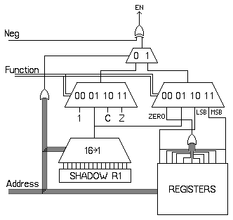
All the conditions can be negated. The condition "NEVER" is created with inverting the condition "ALWAYS".
The condition codes are designed so the condition "ALWAYS" is represented with all the bits cleared (0).
The "shadow" register is currently undefined. In the first iterations, it will be a copy of the R1 register. Later it can be configured to access I/O pins for example.
To be completed... (conditions, autoupdates...)